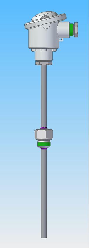
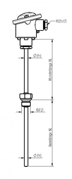
Structure of the fitting:
Structure Form 2G in accordance with DIN 43772
Protective tube diameter 9 – 14 mm of material 1.4571.
Welded screw neck G1/2” or G1” of material 1.4571 in accordance with DIN 43763, extension pipe with diameter 9 – 14 mm of material 1.4571;
Connection head of light metal Form A or Form B in accordance with DIN EN 50446 (DIN 43729) with cable entry M20x1.5.
(For variants please refer to the worksheet).
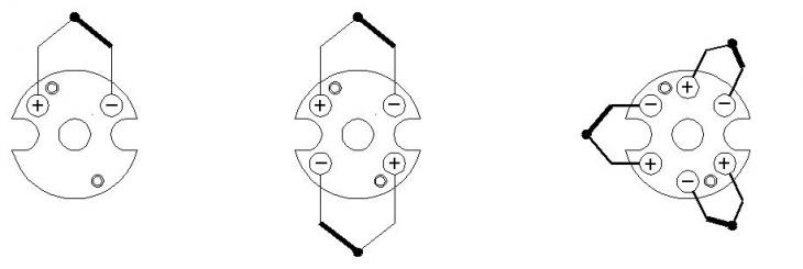
Structure of the inset in accordance with DIN 43735:
Thermocouples 1(2) x Type “J”, “K” and “N”, Basic values in accordance with DIN EN 60584, Tolerance class 1 or 2; Type “L” in accordance with DIN 43710, Tolerance class 2, insulated or welded to the ground. Inset pipe of stainless steel with a 6.0 mm (8.0 mm) diameter; Alternatively in flexible version as mineral insulated sheathed thermocouple inset of 6 or 8 mm diameter of stainless steel or Inconel material. Shelf plate with connection socket.
(For variants please refer to the worksheet).
Design of the thermocouples:
Max. temperatures according to DIN for element type:
Fe-CuNi, Type “J” 600°C Fe-CuNi, Type “L” 600°C
NiCr-Ni, Type “K” 800°C NiCrSi-NiSi, Type “N” 800°C
Even pressure resistant and high pressure resistant versions can be delivered; Additional type specification “HD”. For pressure resistant and stable flow versions, refer to the section Special versions or ask our technical customer service.